We discussed the basics of mill-turn CNC technology in a past blog article. Today, I would like to build on that basic foundation.
One area of confusion to many operators is tooling, especially the tool holder orientation descriptions (radial tools vs. axial tools). Hopefully we can clear that up. I would also like to discuss the use of different tooling options to conserve turret stations when running parts that have lots of features and cutting operations. Machining intricate parts without running out of tooling stations is a common struggle when creating parts on a mill-turn CNC machine.
Let’s say that you are running a machine that has a 12-station turret, and once you begin to load all of the tools that are necessary to complete the features on the part, you realize that you don’t have enough space for every tool. What do you do? Well, you actually have two foreseeable options:
The first option is to simply run the part in multiple setups, machining most of the features in the first setup, and then setting up the machine to run the remaining features on a separate setup operation. Although this isn’t the most efficient way to solve this issue, it would definitely work!
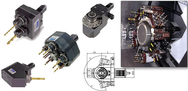
The second option is to solve the problem with commercially available multi-tool toolholders. These toolholders will allow you to mount more than one tool in each turret station and are capable of holding two, four, or even six tools in one single station. Although a Y-axis is necessary for many of these types of holders, it is pretty simple solution to a quite complex problem.
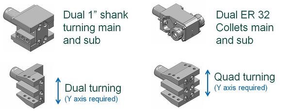
Not only can creative tooling holders and options help solve the challenge of limited turret stations, they can also be used to address many other tooling necessities, such as fixed angled tools, adjustable angled tools, slitting tools, and tooling created to turn flats on parts (polygon turning) extremely fast.
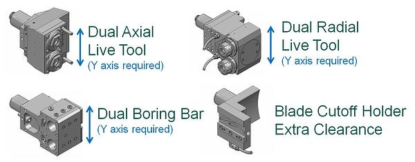
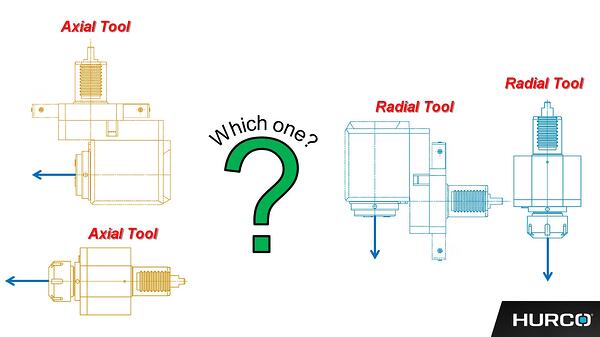
Now we need to discuss toolholder orientations: radial tools vs. axial tools. Although the industry is pretty consistent as far as the description of the actual toolholder body, it is when we begin to discuss programming these tools, and how they actually mount in the turret, that the confusion begins. When you are dealing with tooling companies (like Benz or Eppinger), any of the right-angled toolholders you purchase are considered radial tools, and all of the straight holders are axial tools.
However, when programming, it isn’t quite that easy. Since I am a dedicated Hurco-ite, I will talk about how we handle this conundrum; but each builder and programmer (especially when programming conversationally) has to address it in some manner.
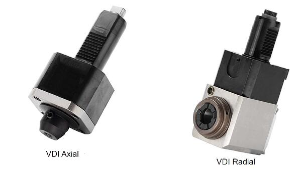
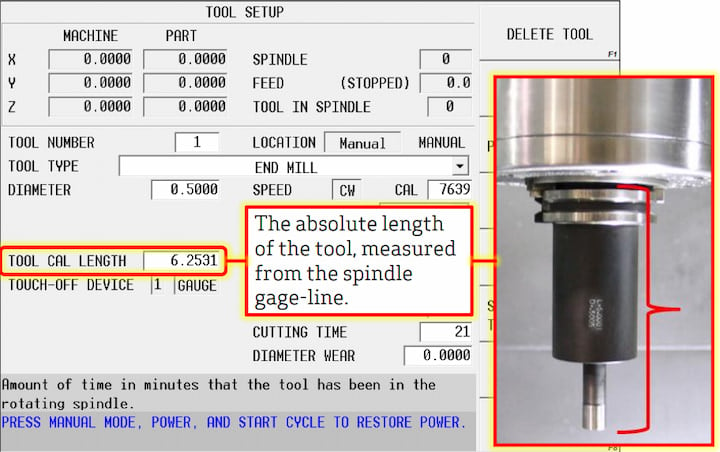
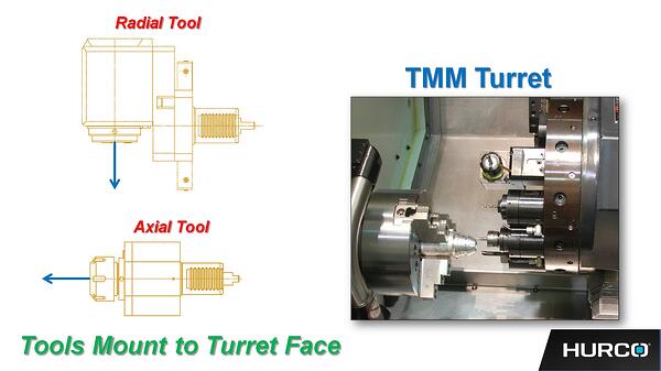
To understand the challenge correctly, you must realize that there are two common ways in which the tools mount in the turret: either directly on the face of the turret, or around the outside circumference of the turret. Not to mention, there are even two separate types of turret mounting conventions (VDI and BMT); but that is a topic for another day. For our purposes, let’s focus on the VDI type (pictured above).
If you were to mount one of each style of toolholder into a face-mounted turret (right angle and straight), you would have the straight holder pointing toward the chuck, and the right-angled tool pointing toward the center of the spindle, parallel to the X-axis. However, if you mounted them both in a turret where the tools mount around the circumference, you would have the exact opposite condition.
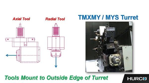
To program live tools in the Hurco control, we need to standardize the difference between a radial tool and an axial tool. We decided to use the direction the tool tip is pointing, regardless of what type of holder it is mounted in and what type of turret it is attached to. If the tool tip lies along the Z-axis, we call it an “axial tool.” If the tool tip lies along the X-axis - which controls the radius of the part - then we call it a “radial tool." Once you understand this standardization of the tooltip orientation, programming live tools, especially using the Hurco conversational control, becomes a breeze!
For more helpful tips and videos, subscribe to our blog and check out Hurco Connect!