Previously, I posted an article titled “5-Axis Machining: It just ain’t that scary,” and to date it has been one of the most popularly read articles in my blog series. So, I'm expanding on that article and diving deeper into what can be done with 5-axis machining to show that even the advanced features of 5-axis really aren't anything more than multi-axis common sense, when you break it down.
With all the hype surrounding 5-axis machining over the past several years, it has been relatively easy to educate machine shops on the benefit of switching to a 5-sided – or 3+2 processing platform – to help make their shops more efficient and ultimately more profitable.
However, we regularly hear the argument that, although they can see the benefit of running parts in only one setup, they believe that they can only run one part at a time, and that simply isn’t true. With a little creativity in fixturing, or by utilizing some of the professionally manufactured OEM fixturing that is available in the marketplace, you can easily add more parts to the process – and even fully or partially automate the process if desired.

I recently worked with a customer who was running a simple rectangular-shaped manifold. Five sides of the part had simple features such as ports, threaded or tapered holes and O-ring grooves, and he needed to process the part in as few setups as possible. It was the perfect candidate for a 5-sided, or 3+2, process!!!

After looking at the part, he realized that he could take this simple process to the next level by using a commercially available fixture with four vises mounted on a 20° pyramid. This fixture will allow him enough clearance to reach all five sides of all four parts, including one angled hole, and he will be able to pull off four complete parts every time he opens the doors with only ONE PART SETUP!
Just think about that. Since this is a repeat job for this shop, they can easily switch from one complex job to the next very quickly. They are able to complete multiple operations, on multiple parts, in just one setup after acquiring one easy-to-find work coordinate.

So, how hard is the programming for this, you ask? I bet you are thinking that it must be a nightmare to keep track of all of those separate parts, and all of those part faces and ever-changing angles. Well, would you believe me if I told you that it was really pretty simple?
Since this is article number two in a series, I am going to begin explaining this process where the other article left off. If you need to refresh your memory, or want to learn more about programming a 5-sided part, please reference either my previous article by clicking here, or take a look at this short video series on 5-sided programming: click here for training videos.
To begin the process of repeating and optimizing a program, we must first have a program to repeat and optimize. Using the principles taught in the previous article, or in the online training videos linked above, let's assume that we have created a successful part program for one single workpiece, but after proving out the program, we have decided to fixture this in a multi-sided fixture and optimize the entire process to be more efficient after the fact. Let’s also assume that this part was programmed from a reference point that is located on the center bottom surface of the part itself (we will use the customer part referenced above).
Now, if we had decided to use the multi-sided fixture from the beginning, we may have tackled this process a little differently. But, since I am trying to show that even a change in the process mid-stream shouldn't be any cause for alarm, we will use some simple control features to accomplish this task.
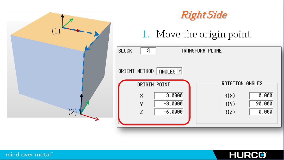
Once the parts have all been loaded onto the fixture, the first thing we need to do is relocate the origin point from the previous reference point located on the single part to the new location that we will use for this new process. Because we are running multiple parts on a round fixture, the most obvious place to reference for machining would be the top center of the fixture itself. Because we don't want to re-program the part, we will account for this position variation with a transform plane block.
A transform plane is typically used to re-orient and locate a temporary change in workplane, but here we will use it to temporarily relocate and orient an entire part program. Because transform planes can be stacked – meaning that if not canceled, a new transform plane will be an incremental change from the previous transform plane – we will keep this first one active until the end of the program, and the entire process is complete. Then we will cancel it.


In this example, the first part on the fixture (at the 3 o'clock position) is located 3.845" in the positive direction along the X-axis from the center of the fixture, and 1.393" positive in the Z-axis (reference image above). Therefore, we will enter these values into the XYZ fields for the "origin point" of the transform plane.
Now that we have relocated the entire program into position, we must tilt it 20° around the Y-axis to align it with the fixture. To accomplish this, we will enter a positive 20 into the "rotation angle" field for rotation around the Y-axis. The example below is showing a conversational program block, but the same thing could be accomplished in NC with the code: G68.2 X3.845 Y0 Z1.393 B20. The G68.2 designates a transform plane, the XYZ are used to relocate the reference point, and tilting around the Y-axis is a B-axis change.

Now that the first piece has been tilted and relocated, we must now address the other three parts on the fixture. We will do this by "looping" the previous step, and execute the part program again at the remaining 90° intervals. This step will be accomplished with a "transform plane group" command. The transform plane group allows us to pattern a transform plane in any direction, and in this case, rotate (or loop) it four times, around the center point of the fixture, in the Z-axis, every 90°.

The last thing we need to address is tool changes. Because this program uses more than 20 tools, and the program was written to run just one single part, when we run it on the machine it would complete one entire part before moving on to the next one – not very efficient.
To battle this dilemma, we will turn on "toolchange optimization." The TCO block will optimize toolchanges so that each time a tool is placed into the spindle, the control will look through the entire process and determine how many times, and at what locations, a particular tool is utilized. It will then then execute all of those processes before completing another toolchange. This will reduce the number of toolchanges from 80 – which would be necessary to run each part complete before moving on to the next part – to only 20, which is the number of tools used in the part program.

The final result is four finished parts in one single operation, located on a multi-part fixture, from one simple part program, and with only one easy-to-locate part setup. Now, wasn't that easy?

To learn more about 5-axis technology, please watch our 5-axis webinar, visit our educational website 5-axis.org, or check out Hurco Connect, where we offer training videos on 5-axis and a variety of other topics.
Don't forget to subscribe to the CNC Machining Blog! You'll receive an email notification whenever a new post is published.