While the concept of having a Y-axis on a multi-axis live tool CNC lathe is simple, the non-orthogonal way the axis moves, and the ins and outs of those movements, can be a little more complicated than expected. So, in this blog I explain the Y-axis movement and how overtravel can occur.
When we jog the X-axis or Z-axis on a lathe, it is simple to understand how the machine will behave to accommodate those movements. Both axes ride along precision linear rails that stretch the full distance of travel for each axis. The travel for each of these axes will add to the determination of the overall size of the machine itself. The longer the Z-axis travels, the longer the bed of the machine will be, for example. But when jogging the Y-axis, it’s not quite as straightforward (figures 1b & 1c).
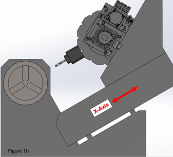
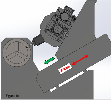
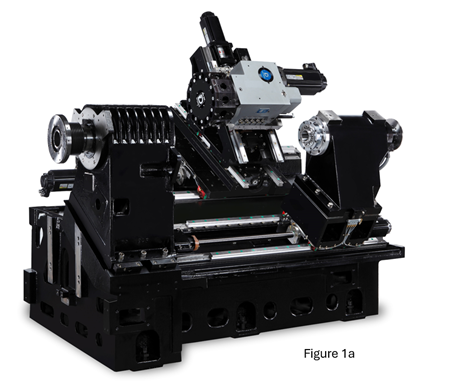
On most multi-axis lathes with a Y-axis, the movement is non-orthogonal, which simply put means that the movement is not a linear or perpendicular 90-degree movement. Jogging of the Y-axis is made possible using a wedge design in the machine where the perpendicular travel is actually achieved by moving two separate parts of the machine (figure 1a).
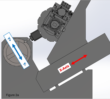
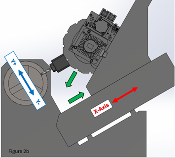
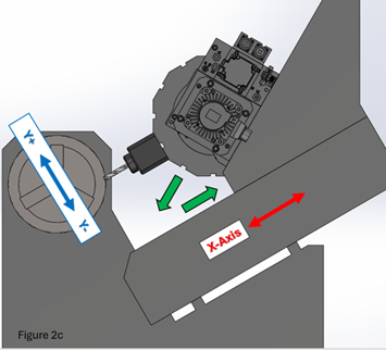
When the control receives a Y-axis movement command, it’s the combined movements of these two pieces that form the wedge that will affect the movement of the tool tip as desired (figure 2a, 2b, and 2c). Again, we ultimately get what appears to be a perpendicular orthogonal movement of the axis, which is made possible by the non-orthogonal movement of the machine components.
This Y-axis motion also allows us to utilize multiple tools in each tool station by providing the ability to shift the axis and teach multiple tool offsets for the same turret station (figure 4a). This capability is not only limited to live tools, but also static stick tooling of both double and quad holders. The quad holders can also expand this multi-tool capability for use on sub-spindle machines as well for secondary operations (Figure 4b).
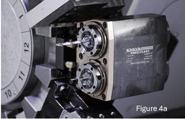
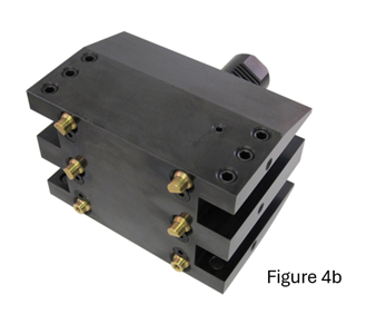
(Figure 4a by EXSYS Automation; figure 4b by Modern Machine Shop)
Now that we understand what is entailed in moving the Y-axis, let’s discuss one of the issues that can be created by this movement when the turret moves to a designated location for a tool change. Since the commanded position of the X-axis for tool change positions references the tool tip, let’s assume that the Y-axis is NOT at the zero or home position (center of the Y-axis stroke), and the X-axis commanded position is well within the travel limits of the machine. We still get an “out of travel” alarm, causing the machine to stop. Why did we get this error?
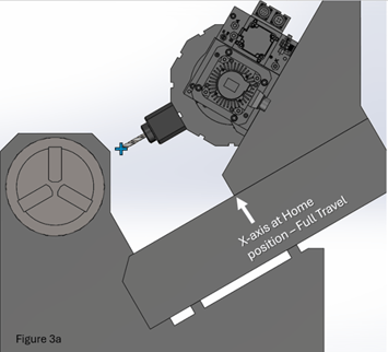
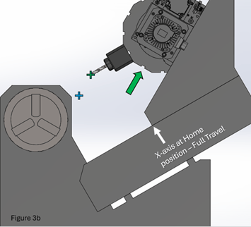
The images below should help clarify the reason for the out of travel error. In figure 3a, we see the X-axis at its full travel position, and the Y-axis is at its zero or home position. In figure 3b, we see the tool tip travel to a positive commanded position of Y 50. The turret can easily move to that location by simply sliding along the wedge without the need to move the X-axis cross slide at all.
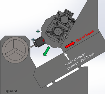
However, in figure 3d, we see that the commanded position would require both the wedge and the X-axis cross slide to move in order to reach the commanded tool tip position – the wedge would need to move negative, and the X-axis would need to move positive - but the X-axis is at a point of full travel and cannot move any further in the positive direction, so the control will produce the error and stop the machine.

If the condition mentioned above was during a machining operation, and the commanded position was out of the travel capabilities of the machine, then a programming correction would need to be made. Or, possibly changing the length of the tool being used or the holder type might both be ways of handling this issue. Either way, it would be up to the program and operator to solve the problem.
On the other hand, if the issue was created while the machine was moving to a designated tool change position, then we do have the possibility of addressing the issue inside of the control software, which is how Hurco has decided to correct the issue. Whenever the control sees that the turret is being commanded to the tool change position, the Y-axis will automatically return to the home or zero location to eliminate the possibility of the out of travel limit error.

You'll find more helpful resources, such as training videos and webinars, at Hurco Connect.

Don't forget to subscribe to the CNC Machining Blog! You'll receive an email notification whenever a new post is published.