When programming in 5-axis, we have two distinct options that we can use to command rotary moves and positions. We can output the data using either rotary angles or tool vectors. Although each one has its pros and cons, I prefer to configure a postprocessor to output these rotary commands as IJK tool vectors, instead of the more common ABC-axis rotary angles.
Using IJK tool vectors makes the program independent of any particular machine configuration. Since we aren’t commanding any specific axis callout (A, B or C) the machine is free to use whatever axes it has available to position the tool to its commanded position and tilt angle. This freedom allows the same part program to be shared among several different machines in the shop regardless of the machine configuration and can offer a tremendous amount of freedom when scheduling jobs on the shop floor.
Tool vectors can also make post processor creation easier as well. When programming a 5-axis toolpath using a CAM system, the software will automatically compute the commanded moves internally using tool vectors. Therefore, it would stand to reason that a post processor that can simply output these previously created moves, without having to translate them, would be much simpler to create. If we configure the post to translate every move into an A-axis, B-axis or C-axis command, then the post processor will have to do more work and in turn be more complex and take more time to configure and test.
So, what is a tool vector? Tool vectors are simply IJK values in a program, added to the end of an XYZ position, that determine what angle and direction the tool should tilt away from the commanded XYZ position. For example: a tool vector command of G01 X10. Y10. Z10. I0.5 J0.5 K0.707106 would be the same tool and axis position as calling G01 X10. Y10. Z10. B45. C45 without having to call out specific axis commands. The second command could only be utilized on a machine with a BC machine configuration.
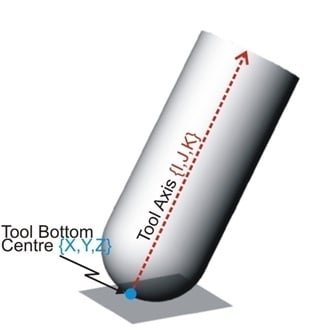
Although tool vector data points are not measured distances and have no unit of measure associated with them, this is how I see them in my mind when trying to visualize a commanded tilt angle of the tool. The three letters used in a vector correspond to the three axes of the machine; I falls along the X-axis, J along the Y-axis, and K is in the Z-axis direction. For visualization purposes only, in the example below let’s assume that each IJK token is a measurement in inches. From the XYZ tool contact point, assume a point in space that is .5” positive in the X-axis, .5” positive in the Y-axis and .70716” up in the positive Z direction. Now in your mind, picture a line that begins at the center of the tool tip and extends upward through the point in space that was created by the IJK tokens. That would be the commanded tilt angle and direction of the tool. It’s just that easy!


There is one last thing that we must discuss when talking about using tool vectors to program in 5-axis. When you allow the machine to determine how it is going to use its available rotary axes to position the tool to the commanded tilt angle, and we recognize that there are at least two acceptable solutions for every 5-axis combination. We have to determine a way to force the control to choose the one that best suits its individual machine configuration. We do this by applying something called “tilt axis preference” — a setting within the control parameters for each machine tool control capable of programming with tool vector input.
Tilt axis preference is used to force the solution of the current 5-axis command that is the best suited direction of rotation for the machine the program is being executed on. For example: on a trunnion machine, where the A-axis can tilt 110 degrees in the negative direction but only 30 degrees in the positive direction (like any of the Hurco 5-axis trunnion machines), we need to do what we can to “force” the control to always tilt negative when possible, ensuring that we have enough axis travel to complete the move.


You'll find more helpful resources, such as training videos and webinars, at Hurco Connect.

Don't forget to subscribe to the CNC Machining Blog! You'll receive an email notification whenever a new post is published.