I was recently asked to explain the motion control system used in CNC machine tools to someone in my family. Realizing that this individual didn’t have a background in manufacturing, and certainly had no experience with anything this complicated and technical, I had to relate my explanation to something common and simple: like driving a car.
 Although this topic is very complicated and technical by nature, I think that this analogy does a pretty good job of simplifying the subject, yet still affords people who are interested an adequate basic understanding of what is happening. Obviously, such an advanced technological subject could take the better part of a semester in college to gain a thorough understanding, but for us simple folks, I think the driving analogy will work just fine. But, before we begin, we need to lay some groundwork. You need to understand the basics of how a command that begins within our brain travels through the CNC control, and finally manifests itself as a movement of one the machine’s linear axes.
Let’s think of our part program (conversational or G-code) as nothing more than a list of commands. Those commands are organized by the CNC control and arranged into different categories for each of the individual axes of the machine. Then they are passed along to the corresponding axis. Once the command has been received by the servo drive for a particular axis, that command is broken down into a simple voltage requirement necessary to move the axis as ordered by the command. That voltage is then applied to the motor, causing the motor to spin, and thus causing the axis to move.
As the axis is moving, its current position is continually monitored by an encoder mounted on the end of the motor, or a glass scale that is mounted along the length of the axis. This monitoring device provides feedback to the servo drive so changes in the voltage commands can be made if necessary. More voltage means the motor spins faster, and the axis catches up if lagging behind; less voltage means the motor spins slower, therefore slowing the axis if it is beginning to run too far ahead of the commanded motion.

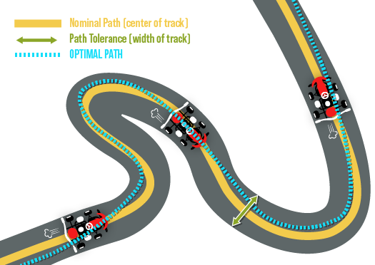
(Illustration showing differences in toolpath obedience rate for cornering speed)
Now, with that out of the way, let’s apply our driving analogy. First, we need some commands to follow. Let’s say the route in which we will travel to our final destination is our cutter toolpath, and the speed limit signs along the way will act as our commanded feedrate. Your brain is the CNC control, your muscles will act as the servo drives, and your extremities can be the servo motors that control your axes. We will use our eyes and the speedometer for feedback. Now, because nothing in life can be perfect or exact, we need to allow for some acceptable tolerance to our commanded positions. Let’s say the entire width of the road is our positioning tolerance, and as long as we stay on the blacktop, we are good to go.
In this first analogy, picture yourself parked on an abandoned highway in the middle of nowhere, and the road is laid out as straight as an arrow in front of you. You have been commanded to travel for a distance of one mile, following the double yellow line in the middle of the road, and the speed limit for this road is 100 mph. To begin, your brain tells the muscles in your foot to apply pressure to the gas pedal, and the car begins to move. To follow the yellow line your brain will use the visual feedback from your eyes to control the muscles in your arms and keep the vehicle moving in a straight line. Depending on the feedback received from the speedometer, your brain will also have to control the muscles in your ankles to increase or decrease the pressure being applied to the accelerator to maintain the commanded speed of 100 mph. Positional tolerance really isn’t an issue here. Okay, I realize that was extremely simplified, but now that you see how my driving analogy can be applied, we can take it further.
Using the same commands as above (following the double yellow line for one mile, at a speed of 100mph, and using the entire width of the road as our acceptable tolerance), let’s move along to analogy number two. We are sitting in the middle of the last bit of straight road that we will encounter for the next mile. The road laid out in front of us is windy and hilly, and operating within our commanded restraints will be a bit more challenging this time. We accelerate up to our commanded speed of 100 mph but are quickly presented with our first obstacle: a full 90-degree turn to the right.
Realizing that we cannot successfully navigate this turn and still maintain our current speed, we have to reduce our speed. We must find a smooth trajectory through the turn that will allow us to maintain a speed that is as close to our commanded speed as possible but doesn’t cause us to run off the road. Reacting to the feedback received from our visual devices, our brain sends the commands to control the necessary movements and adjustments our speed and trajectory path to successfully navigate the turn.
Then, almost immediately, we find ourselves facing an even more challenging obstacle: an “S” curve with an uphill climb in the first half, and a downhill run in the second half. Although this situation would be handled much like the simple 90-degree turn above, we now have to react to the changes in elevation as well. We increase the pressure to the accelerator while climbing the first section of the turn and decrease that pressure, and apply the brakes if necessary, on the last section so we don’t exceed our commanded speed of 100 mph when gravity begins to take over. This action and reaction will continue for every obstacle we encounter until we have reached or final destination… the end of the program!
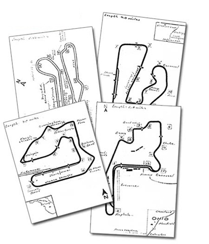
When talking about motion control, we must also discuss something called “block look-ahead,” which is usually measured by the number of blocks the control is able to process in advance. This allows the control to better prepare itself for upcoming obstacles.
In our driving analogy, block look-ahead might be illustrated as an LCD display, mounted in the dashboard that would provide us with a map of the track so we might be able to alter the trajectory on our current obstacle and be in a better position to smoothly execute a future obstacle. Obviously, the more complicated the cutter toolpath becomes, the more available look-ahead that might be necessary to maintain the smoothest and fastest route to the finish line. Although every machine tool builder has a means of handling block look-ahead similarly, some are more effective at it than others.
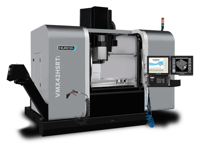
Hurco’s WinMax® control has something called UltiMotion, a patented software-based motion control system that offers a variable block look-ahead that allows the control to see up to 10,000 blocks into the future and can produce reductions in cycle time of up to 30%, especially on the more complicated toolpaths where more look-ahead is needed. Obviously, on the simpler cutter paths like the ones in our first two analogies above, the control will require far less look-ahead than that last scenario. Therefore, more of the control’s RAM memory is freed up and can be better utilized for other things. Controls that don’t have this unique ability to “adapt” to the current needs of the control aren’t able to re-purpose any of the available control RAM memory and can’t benefit from this sort of variability.
ULTIMOTION TECHNICAL PAPER
FIND OUT HOW YOU CAN REDUCE CYCLE TIME BY 30%
You'll find more helpful resources, such as training videos and webinars, at Hurco Connect.

Don't forget to subscribe to the CNC Machining Blog! You'll receive an email notification whenever a new post is published.