 If you asked 10 different 5-axis programmers to program the same single part, you would most likely get 10 different machining strategies. Depending on experience, machine configuration, CAM software, tooling, workholding, and a myriad of other criteria, everyone sees the path they need to travel just a little bit differently. But they all lead to the same place: a successfully completed part. This article will be part one in a multi-part series about 5-axis programming.
parameter settings
When you begin to program in 5-axis NC, you will quickly realize that one of your first obstacles will be to understand the impact of the exhausting amount of control parameter settings. Setting any one of these parameters incorrectly can mean the difference between success and failure when generating your desired toolpath. Each one of these parameters has an important job to perform for tool axis and collision control.
Tool Axis Control
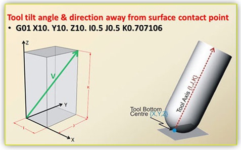
Tool Axis Control parameters dictate how much and in which direction the tool will tilt and how that tilt will be controlled and driven throughout the machining process. Common features like lines, surfaces, planes, points and chains are used to control how a tool’s designated tilt angle will be maintained. Once a tool has been linked to one of the common features mentioned above, the tool will maintain that relationship to the feature, thereby controlling its tilting angle. If a point or line has been designated, for example, the tool tip will follow the programmed toolpath, but the top edge of the tool will always point to the designated point or follow the designated line to maintain the proper amount of tilting specified by the programmer. Similarly, if a surface or plane is selected, the tool will continually keep the designated tilt angle as it relates in reference to the surface or plane selected as the control feature.

In addition to – or in concert with - the use of geometric features, lead, lag and side tilt angles can also be designated to control the tool axis tilt. In the case of a lead or lag angle, the tilt angle designated is in relationship to the direction of travel. Lead angles tilt with the direction of travel, as if it were leading in front of the tool. Lag angles tilt away from the direction of travel, as if the tool was lagging behind the cut. Side tilt angles are designated as positive or negative degrees and will direct the tool to tilt off to the left or right side of the direction of travel.
collision control parameters
The programmer must also learn to use the collision control parameters, which are limits that affect the tool and how much, and in which direction, a tool is allowed to tilt, regardless of the tool axis control method used. Allowing the tool to blindly tilt without any regard to limits can allow the tool or toolholder to make contact with either the workpiece or the machine itself, causing a collision. Learning to use both the Tool Axis Control and Collision Control parameters effectively is one of the things that can separate a good 5-axis programmer from a great 5-axis programmer.
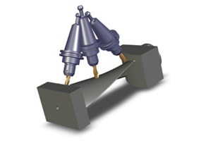
why tilt the tool?
A common question: why we need to tilt the tool in the first place? Why not simply keep the tool vertical to the surface being cut like we do in 3-axis machining? We tilt the tool in 5-axis machining because we can! Tilting the cutter is most common for tooling with a corner radius and not square-cornered tools such as flat endmills. The ability to tilt the tool means that we are cutting on the radius and not on the bottom center of the cutter, which will give allow us better control over chip-load and feedrates and provide us with a much better surface finish and longer tool life. Since the bottom center of a rotating tool has no effective speed, using a vertically aligned tool performs more like it is being dragged, instead of cutting along the toolpath.