Just like any other form of technology within our industry, 5-axis manufacturing has its very own vocabulary and list of technical buzz words. Although many of the features described below can be viewed as common, some are only found on the more advanced machine controls. For anyone looking into 5-axis machining, understanding these buzz words can be a huge benefit - and just might keep them from making an uneducated decision that they might live to regret later on.
Tool Center Point Management (TCPM): also referred to as RTCP by some manufacturers – is one of the more powerful features, and can have a significant impact on the overall multi-axis machining process. TCPM offers the programmer the ability to create programs that are “independent” of the machine coordinate itself, and allows the user to simply reference a single point on the actual workpiece when setting up the job or programming the part – without concern for where the actual part location is on the machine. Without TCPM the point data in the program must reference movements relative to the machine coordinate and centerlines of rotation, and all programming is “dependent” on the actual location of the workpiece within the machine’s work envelope. For example: without TCPM, the part must be located and clamped in place on the machine before the program can even be created, and the actual distance of the workpiece from the machine centerlines must be accounted for in the program...which is usually accomplished by physically moving the solid model in CAM space, the exact distance from zero as it is in the machine. This is why we say the program is DEPENDENT on the machine coordinate without TCPM. Without TCPM, if small adjustments must be made, the operator would have to go back to the CAM system, move the solid model the necessary amount, repost the program, reload the program in the machine, and try the cut again. On a machine with TCPM, in this same scenario, the operator could make a simple adjustment to the part setup or work coordinate, and run the part again. Hopefully you can see that the use of TCPM will also make things A LOT easier the next time you have to setup the same job.
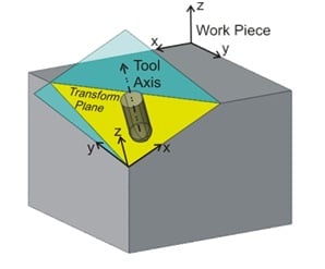
Transform Plane: a workplane that is positioned in reference to our original machine coordinate workplane. If you think about it, Transform Plane is really the magic that makes 5-sided programming so easy, and what allows us to control all five sides of a workpiece individually within one single program – first by allowing us to reference a different origin point for each side of the workpiece, and secondly by allowing us to designate a flat work-plane to control our cutter during machining. Since features on a blueprint are most often drawn in reference to a single point on each side of the part (and not usually the same point we used for our initial part setup), the ability to designate these multiple origin points is extremely important. Also, without the ability to transform individual work-planes, canned cycles like the G83 drilling cycles could not be used on any face of the workpiece except the top side…because the tool axis must be perpendicular to the side of the workpiece being drilled.
Surface Normal: this is actually not a machining term at all, but most definitely becomes a necessary buzz-word to be familiar with when programming in 5-axis. The term refers to an axial vector (or line) that is perpendicular to a particular surface on any solid model. Solid models are constructed by joining a multitude of surfaces together, to create a given shape. A programmer will always designate a tool tilting vector that is in reference to the surface normal. For example, if you want the tool to stay vertical to each surface as the cutter moves along the shape, you would say that the tool is “normal to the surface”. Consequently, if you wanted the tool to tilt to one side or the other as it moves along the shape, you would designate a plus or minus tilt angle…and that angle would be in reference to the perpendicular surface normal.

Tool Vector: refers to the angle in which a tool tilts away from the XYZ contact point. This angle is controlled by a set of IJK values on each line of G-code in a program, and the values can be either positive or negative numbers. Although vectors have no relative units of measurement - and are neither metric or inch values - for simplicity I find that it helps to think of these values as measured distances when visualizing the designated tilt angle and direction…for example: if I see the line of code X2.0 Y2.0 Z.125 I.50 J.50 K.70 in a program I can easily visualize the tool tilt angle in my head. The XYZ values are obviously used to position the bottom center of the tool at the designated location, and the IJK values designate the direction and amount of tilt – the letter I is synonymous with the X-axis, J is synonymous with the Y-axis, and the K is synonymous with the Z-axis. Therefore, picture a point that is .50” positive in the X axis from the contact point, .50” positive in the Y axis, and up .70” in the positive Z direction. Now, visualize a line drawn between the XYZ contact point and the point in space created by the IJK distances…that is the tools designated tool vector.

Toolpath Linearization: the ability to control the tooltip in a linear fasion between two points. Without the feature, the programming only has control over two points in a movement of the tool’s tip – point “A” at the beginning of the move, and point “B” at the endpiont of the move. Everything that happens in between these two points is uncontrolled, and you can say the machine “blindly” makes the move. However, with tool path linearization activated, the machine will coordinate all axes of the machine to insure that the tooltip moves in a linear movement – between the two points – and will even raise or lower the Z-axis if necessary. In the example images below you can see that without lineariation active, the tooltip would gouge the part dramatically…but with linearization activated, the tool moves in a straight line between the start and end points. Not only does this allow for more control of the tooltip during machinng, but it also can result in smaller programs…because the moves don’t need to be broken up into such small moves to make up for the lack of adequate tooltip controls.

You can learn more about our full lineup of 5-axis machining by visiting https://www.hurco.com/5axis