The Hurco control is so easy to use and self-teach that often times there are overlooked features that could be extremely useful if operators knew about them. This blog article is to help machinists understand some features of the WinMax® software they may not have been aware of.
Work Offset in Conversational Programs (G54-G59, 93 Auxiliary Offsets)
There are often times when there is a need to switch between different setups on the machine, like when you have multiple operations set up in different vises on the table. Previously, the operator had to input a "Change Part Setup" into the program each time they wanted to switch to a different setup coordinate, and another one to switch back. This is problematic because if a small shift is necessary in the X-axis, for example, then the operator would need to locate every single "Change Part Setup" in the program that referenced that particular location and make the change, which could easily be dozens of places throughout the program.
However, by using the "Work Offset" feature, the change can be made in one single location (G55 for example), and everywhere that particular work offset is called, the change would be utilized. The "Work Offset" block is located in the conversational programming section under the "Miscellaneous" tab (Miscellaneous, More>, Work Offset).
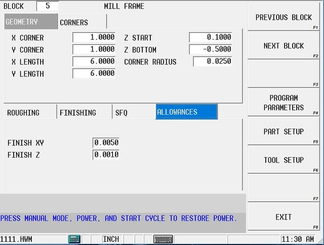
Stock Allowance Tab
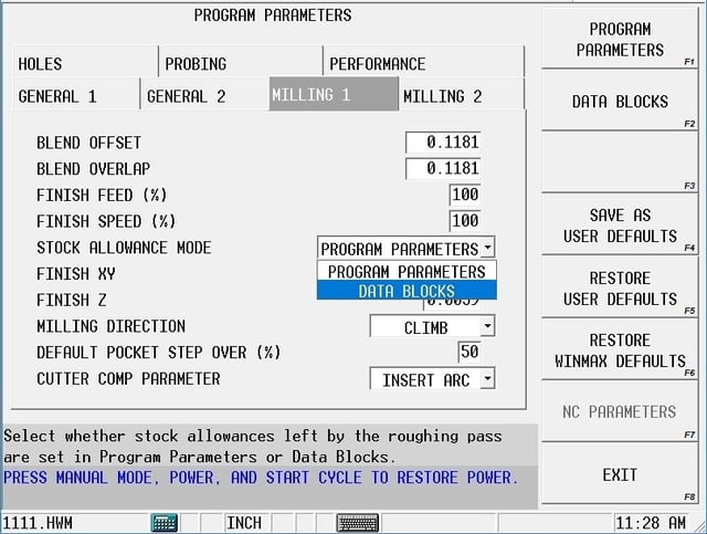
Historically on the Hurco control, the amount of stock left for finishing allowance was a global setting that was located in the "Program Parameters" for any given conversational program. The challenge with this global setting becomes apparent when you need to change the amount of stock left for a particular block, or if you want to leave grind stock on a feature before heat treating, which would mean that you needed to lie to the diameter of the tool or the size of the feature. However, by turning on the "Stock Allowance" tab in "Program Parameters," both of these challenges can easily be addressed.
With the "Stock Allowance" tab active, you can set the amount of material that will be left for the finish pass in each conversational block of the program independently. To alleviate the need to lie to the control when leaving grind stock, the allowance stock will not be removed if you don’t program a finish tool. This can also be helpful when stress-relieving a part during machining. Simply leave the stock now, copy and paste the block into a different location later on in the program, and then remove the allowance values.
To change the setting so the control will allow the use of the "Stock Allowance" tab, go to "Program Parameters," select the "Milling 1" tab along the top of the page, and set the "Stock Allowance Mode" to "DATA BLOCK." Remember to save this setting as a "USER DEFAULT" if you want this to become the new default setting for future conversational programs.
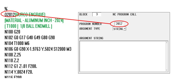
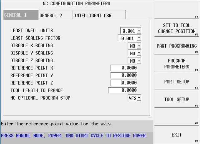
Setting Reference Return Position for NC Programs (G28)
In many NC programs, the use of the G91 G28 XYZ reference return position is very common. As a default setting, this code will send the machine to the home position for each axis. However, Hurco has provided a setting in the NC parameters that will allow the user to designate where the machine should travel when the G28 command is executed.
With an NC program active, select "PROGRAM PARAMETERS" from the "INPUT" screen, select the "NC PARAMETERS" softkey, select the "NC CONFIGURATION PARAMETERS" softkey, and set the desired location for X, Y and Z reference return points.
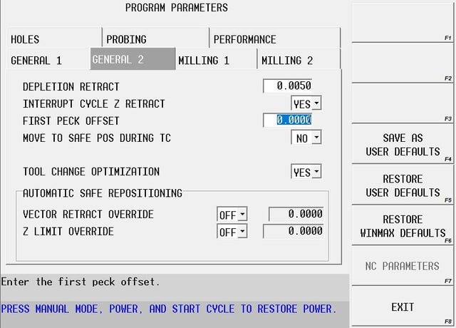
First Peck Offset
Every conversational programming block has both a "Z START" and "Z BOTTOM" field for designating the rapid point and final depth of any feature in the Z-axis direction. These blocks also have a "PECK DEPTH" field as well. Sometimes, depending on the values, the tool will cut a lot of air while pecking before it actually contacts material. The "PROGRAM PARAMETERS" setting for "FIRST PECK OFFSET" can help alleviate this wasted time.
For example, when inputting a "Z START" of .100” and a "PECK DEPTH" of .025”, the control will begin pecking at a location of .100” above the part. Therefore, it will take five full pecks before the tool actually begins to remove material. By setting the "FIRST PECK OFFSET" parameter to a value of .100”, the control will force the tool to position at the "Z START" location, offset or shift down the amount of the "FIRST PECK OFFSET," and begin to peck from that new location. In this example, material would be removed on the very first peck, and therefore, eliminate any wasted time. This parameter can be found on the "GENERAL 2" tab of the "PROGRAM PARAMETERS."
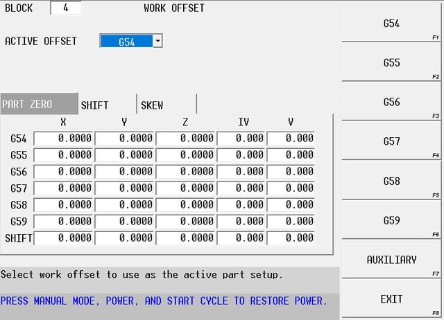
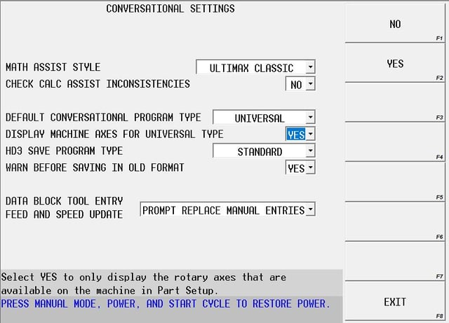
Display Axes Designators (instead of IV & V) with Default Universal Rotary Setting
When you create a new conversational program, the default setting for the program type is "UNIVERSAL ROTARY," which is definitely the setting we would like you to use for many reasons. However, when the program type is set to "UNIVERSAL ROTARY," the part setup screen will display X, Y, Z, IV and V as the axes for the machine, regardless of machine type. On 5-axis machines, this can be confusing because it doesn’t display the actual axes of the machine; on 3-axis machines, it is confusing because there isn’t a fourth or fifth axis available.
To change this behavior, we need to change one of the user preference settings. Press the "AUXILIARY" button on the control panel, select the "UTILITY SCREEN" icon from the pop-up menu, select the "USER PREFERENCES" softkey on the screen, select "CONVERSATIONAL SETTINGS," and set "DISPLAY MACHINE AXES FOR UNIVERSAL TYPE" to a value of "YES."
For 4- and 5-axis machines, this will cause the control to display the actual A, B or C designator for the axes. For 3-axis machines, it will eliminate the display of the additional axes altogether. This will not change the way existing programs behave, and no changes in programming will need to be followed for future programs. This will just simplify the display.
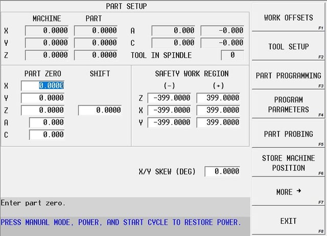
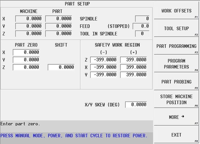
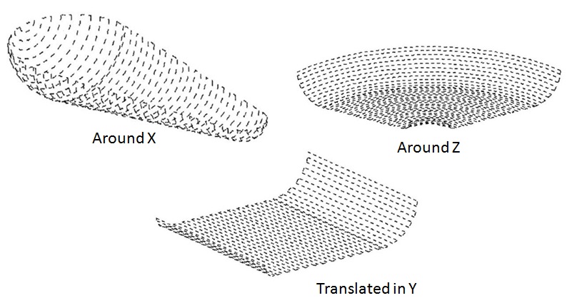
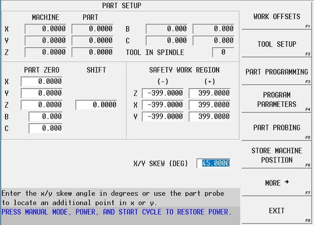
Using X/Y SKEW (DEG) field on Part Setup Screen
By entering a value into the provided field on the "PART SETUP" screen, an entire program can be skewed for any desired purpose. For example, if the program is machined in an un-rotated orientation as normal, but the part must be placed on the machine at a 45-degree angle to allow it to fit into our setup, then a value of 45 degrees can be entered into the provided field, and the entire program will be executed at the rotated orientation.
Although the intended purpose of this field was for probing a part for skew, it has proven to be very useful for manual input of values for reasons like the one mentioned above.
Jog Along Current (active) Work Coordinate System
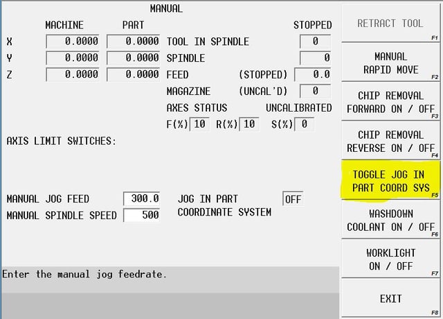
Similar to using the SKEW angle mentioned above for programming, there are also times when you might need to manually jog the machine along the skewed (active) work coordinate as well. To do this, you will simply need to select a mode button in the "MANUAL FUNCTION SETUP" screens.
Press the "MANUAL" mode button on the control panel, select the "MANUAL FUNCTION SETUP" softkey on the screen, and select the "TOGGLE JOG IN PART COORD SYS" softkey. Now with this toggle active, whenever the X- or Y-axis is jogged manually using the jog wheel or jog buttons, both the X and Y axes will jog accordingly, moving the tool along the corresponding edge of the part. To shut this feature off, simply toggle the softkey again. This feature is also available during an interrupt cycle on a 5-axis machine when a transform plane is active.
Click here to download a free 90-day WinMax® trail for your desktop so you can test things out for yourself.
Don't forget to subscribe to the CNC Machining Blog! You'll receive an email notification whenever a new post is published.
You'll find more helpful resources, such as training videos and webinars, at Hurco Connect.