A while back, I received a comment on one of my previous blog posts asking how to designate 5-axis transform planes using IJK UVW vector tokens instead of the traditional ABC rotary axis designations on their 5-axis CNC machine. Instead of just replying to that comment, I thought I would write this post as a response. Since this will be a continuation of the 5-axis CNC basics series, I suggest that you read and understand using IJK tool vectors as a pre-cursor to this article.

The idea behind creating a 5-axis transform plane using vectors is exactly the same as programming tool movement with IJK tool vectors on any machine with a fifth axis. However, the difference lies in the fact that you will have two separate vectors: one using IJK and the other using UVW. The reason you need two separate “legs” for this function is because you cannot designate a plane with only one axis. I will use the floor inside a room as my analogy: you could not create a floor in a room without having at least two walls. With only one, the floor would simply spin around that single axis and could actually point in literally any direction. To accommodate the two legs of the transform plane, and because we want to determine the direction of the Z-axis ultimately, we will use the X-axis and Y-axis as our legs, or walls of the desired transform plane.

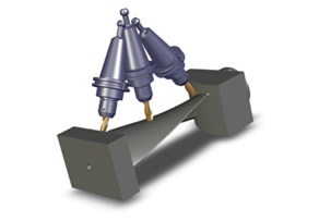
Below is an example of the G-code used to designate the transform plane shown in the image above using IJK UVW vectors (rotating 90 degrees around the Y-axis) on our 5-axis CNC mill. The original part zero was the top center of a 6" x 6” x 6” cube: G68.2 X3.0 Y-3.0 Z-6.0 I0 J0 K-1 U0 V1 W0.
The IJK designates the orientation of the RED arrow (X-axis). The X and Y direction of the arrow hasn’t moved from its original orientation and is still in line with the origin point in both directions. Only the Z-axis direction has changed; it is now pointing downward in the negative Z direction. Therefore, we use the negative one (-1). Had this been a positive one (+1) (I0 J0 K1), the red arrow would have been pointing upward, and the Z-axis would have been oriented to the left side of the part.
The UVW designates the direction of the green arrow (Y-axis). To designate the direction of the arrow, we only need to use a value of positive one (+1) in the Y-axis direction, which coincidently would be the same orientation of the Y-axis if we were machining on the top side of the part. This UVW vector would be the same for any transform plane where the Y-axis is still aligned in its original orientation. However, if a negative one (-1) had been used for the V token (U0 V-1 W0), then the green arrow would be pointing toward the front of the part (180 degrees different), and the Z-axis would have been oriented to the left side of the part.

As you can see, with a little bit of understanding, this really isn’t that difficult to visualize or program. In this example we used a simple 90-degree rotation around one axis, but this same principle could be used to designate any compound angle of rotation necessary for any transform plane required. It is as simple as pointing the red and green arrows in the direction they need to point, and the Z-axis will always point perpendicular to the plane created.