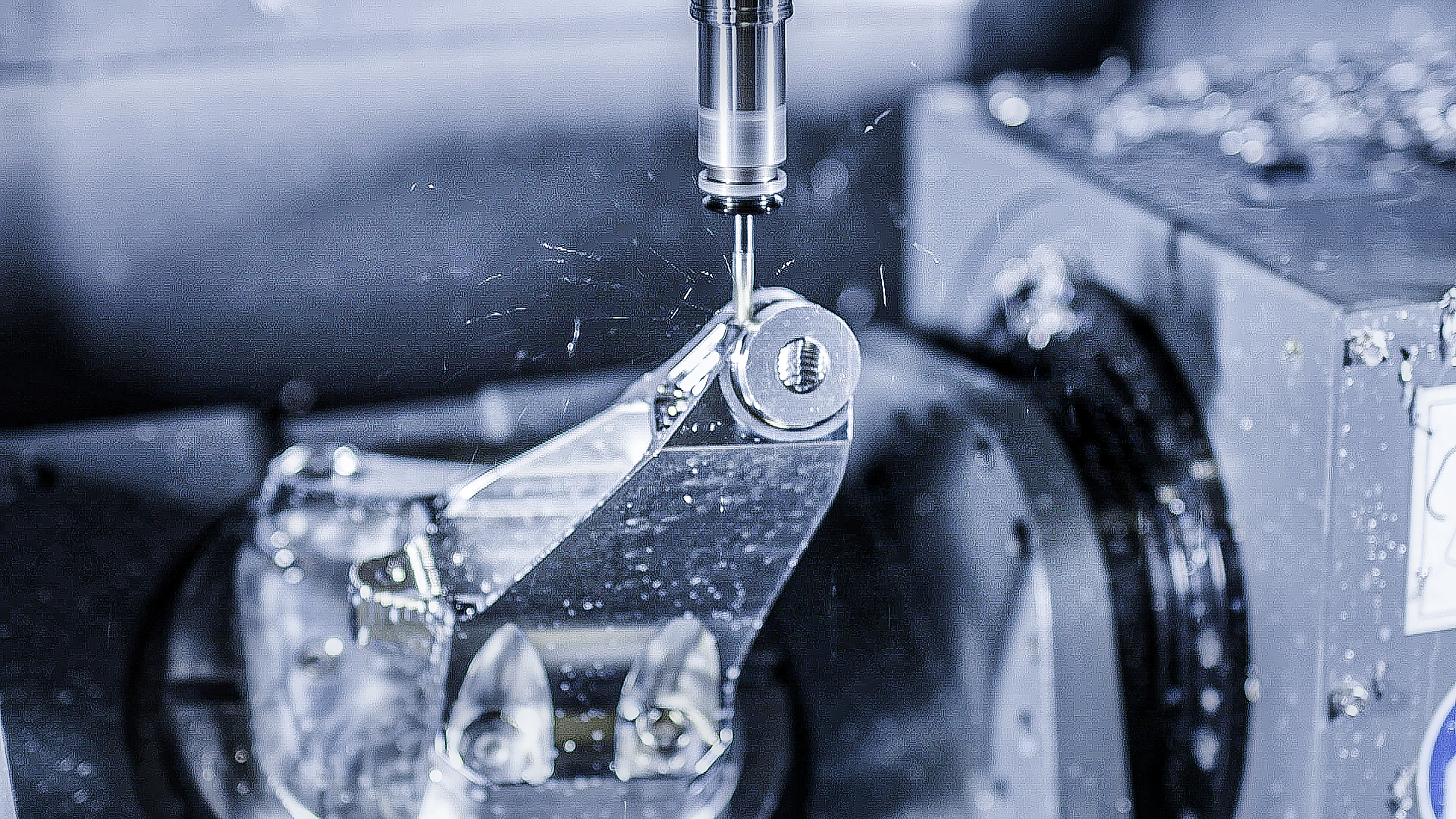
5-axis machining
5-axis machining has become much more prevalent in today’s manufacturing marketplace, and the overall knowledge base of machinists and operators has grown by leaps and bounds over the past several years. Yet there is still a great deal of misunderstanding and mystery surrounding accuracy, both as it applies to the workpiece itself, and also how the overall positioning of the rotary axes of the machine might be affected.
improved accuracy
It is no secret that simply moving away from the traditional 3-axis setup, for parts with multi-sided features, will inherently prove to create a more accurate part. This is because each time the part is flipped and relocated against a mechanical stop there is the possibility of mislocating the workpiece and allowing for inaccuracies in each step of the process. However, by moving to a 5-sided setup, with only one clamping of the workpiece, the accuracy of the overall process will inherently improve, and the accuracy of the individual part should theoretically be as close as the machine tool is capable of positioning. But understanding what factors are in play that might affect the overall accuracy of a particular process is at the heart of creating an accurate workpiece and is what will make the difference between a good 5-axis machinist and a great one.
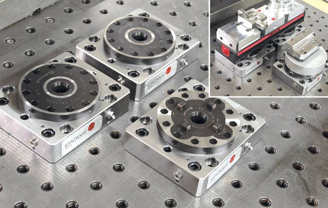
Main components
There are three main components that come into play when we discuss rotary axes: the machine table, axis motors, and encoders. The table is obviously the surface where we mount our workpiece. The motors are used to move the rotary axes when commanded. The encoders provide positional feedback to the control so the machine will be able to monitor and adjust for the current position of each axis. This is all pretty simple, and probably very obvious to anyone who has ever operated a CNC machine. However, how these three components work together is what we must evaluate. The tolerance of any given encoder is pointless if it isn’t providing feedback for the correct components. A couple of key questions that we must ask ourselves: Where are the encoders mounted? What component are these encoders actually monitoring?
rotary axis
For a better understanding of the questions presented above, we first need to breakdown the movements and feedback of a rotary axis. Let’s use the C-axis (rotates around the Z-axis) of a traditional trunnion-style machine configuration. When a position is commanded by the control, the command is sent to the axis drive, which forwards a command to the motor to move the rotary axis. The encoder monitors and reports the feedback of the current position back to the drive, and then the axis drive updates the position to the control. This is all pretty straightforward and easy to understand or visualize. However, what mechanical components were actually moving, and what was being monitored are the true questions.
In the case of many trunnion-style machines, for example, the C-axis is rotated by a mechanical worm-gear that is attached to a shaft and rotated by the motor. As these mechanical components begin to heat up from continued use during the execution of a given program, inaccuracies are inherently injected into the mix of mechanical components. If the encoder is mounted on the end of the motor shaft and only monitors the movements of the motor shaft itself, then the angular position of the actual work surface is not being monitored at all. Therefore, the control isn’t compensating for the positional errors that are most definitely present, and workpiece accuracy is going to suffer. However, if the encoder is mounted in such a way as to monitor the actual position of the table itself, the mis-positioning of the axis - due to the heat buildup in the mechanical components - would be monitored and corrections can be made by the control to compensate.
When dealing with 5-axis machining, it is important that we remember there are actually two separate rotary axes that are essentially stacked upon one another, and given the fact that each individual axis is allowed some positional tolerance, this can also affect overall accuracy of the workpiece and must be considered.
encoder tolerances
Now that we understand the mechanics and how they can apply to all of this, we can dive into the meaning of encoder tolerances. Typically, rotary encoder tolerances are specified in arc seconds: i.e.: +/- 2.5 arc seconds, +/- 5 arc seconds, etc. An arc second is basically 1/60th of an arc minute, or .0003°. It is important to remember that these tolerance specifications are measured from the center of rotation for a particular axis. This means that the farther away from the point of rotation, the more measurable an angular mis-position will be magnified and the less accurate the positioning of a particular feature on a part might be.


conclusion
So, does all of this mean that 5-axis machining isn’t accurate, and that it cannot be used for close tolerance work? No. The intention of this article is to simply point out how all of these factors can play into the accuracy of the overall process and to highlight the care and planning that must be placed on the setup and fixturing of the workpiece. Things like keeping the fixture height as short as possible, therefore keeping the part as close to the point of rotation as possible, can make a huge difference in the overall success of a setup. Armed with the proper knowledge, applied correctly with good machining practices, 5-axis machining can prove to be a real gamechanger in the highly competitive world of manufacturing.