CNC Lathe Bed Design: True Slant vs Flatbed 'Flying Wedge'
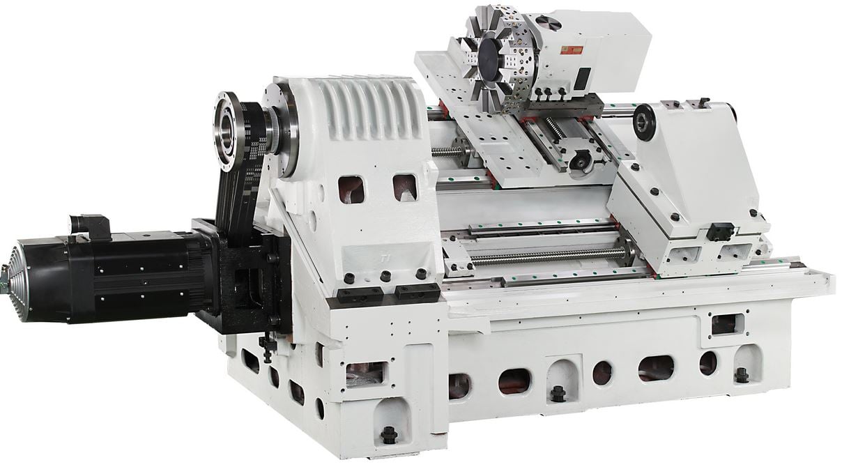
In this article, I discuss the ins and outs of the two main bed designs for CNC lathe machines: the true slant bed and the flatbed “flying wedge” configurations.
When purchasing a CNC lathe, there are several questions to ask yourself before you begin the process. Some of these questions will be quite obvious: how much axis travel do I need? What size chuck should I look for? How many tool stations are on the turret? What is the spindle bore size? Etc.
However, there are other specifications that are just as important but not always so obvious: what is the maximum swing distance that my work will require? What is the maximum turning diameter necessary for my family of parts? What kind of spindle horsepower and torque will my type of work consume? The first set of questions above is relatively easy to answer, but the second group requires a better understanding of lathes in general.
There are several things to keep in mind when you are in the market for a new 5-axis machining center. To be successful, you must make sure that the machine will fit all of your needs, not just your current one. Often times the purchase of a 5-axis machine is driven by a particular job or part, and sometimes shops fail to consider the other work they could run on the machine. Remember, size does matter.
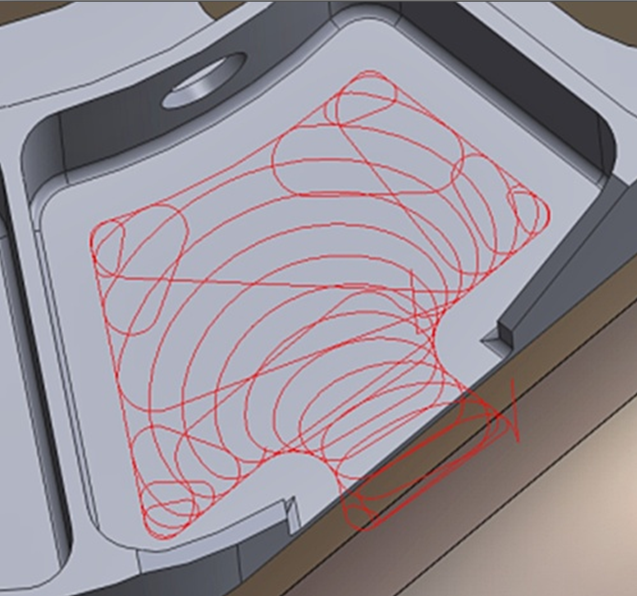
When we hear the term high-speed machining (HSM), most people associate it with mold making. What people fail to realize is that this technology is being used effectively by shops of every kind to positively impact the bottom line — and isn't that what everyone wants?
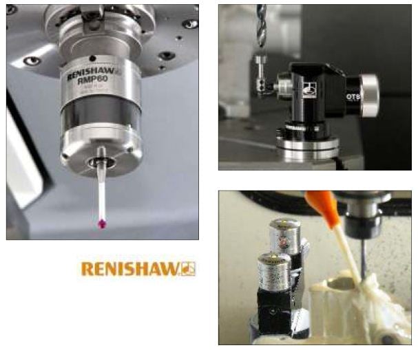
In today’s CNC machining industry, it’s all about quick setup and changeover between parts, especially in an environment where you run a high mix of low volumes. In this article, I want to discuss how part and tool probing can offer a real advantage for the shops that find themselves in this type of environment.
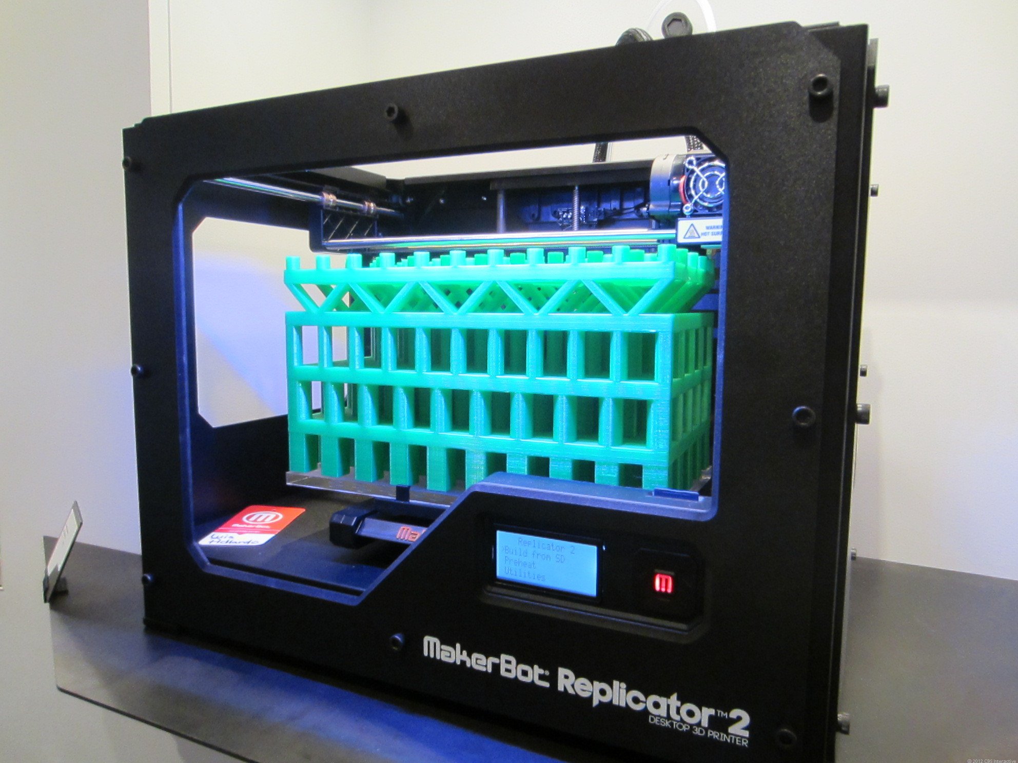
For the past ten years or so, we have seen 3D printing technology – also called Additive Manufacturing – really gain momentum in the industry. In fact, it has become so common-place that there has been speculation by some that it might actually replace traditional manufacturing in the not so distant future. Although I can see many benefits of this amazing new technology, and although I do agree that it will someday impact our lives – such as how we, as consumers, acquire many common household items - I have my reservations about how much it will ultimately change the need for traditional manufacturing processes as we know them. Because of the limitations on mixing printing materials, and the fact that the materials available for use in printing are not always the best for a particular application - not everything that can be printed, should be printed.
Previously, I published a two-part series on the basics of mill-turn technology, where I cover topics such as: axis configurations, the orientation of live tooling holders, mill-turn terminology, instances when a Y-axis might be necessary, etc. In this article, I discuss the differences between the driven tool mounting configurations and offer my opinion on the benefits and challenges associated with each.