5-Axis CNC Mill Programming: Transform Planes Using IJK UVW Vectors
A while back, I received a comment on one of my previous blog posts asking how to designate 5-axis transform planes using IJK UVW vector tokens instead of the traditional ABC rotary axis designations on their 5-axis CNC machine. Instead of just replying to that comment, I thought I would write this post as a response. Since this will be a continuation of the 5-axis CNC basics series, I suggest that you read and understand using IJK tool vectors as a pre-cursor to this article.
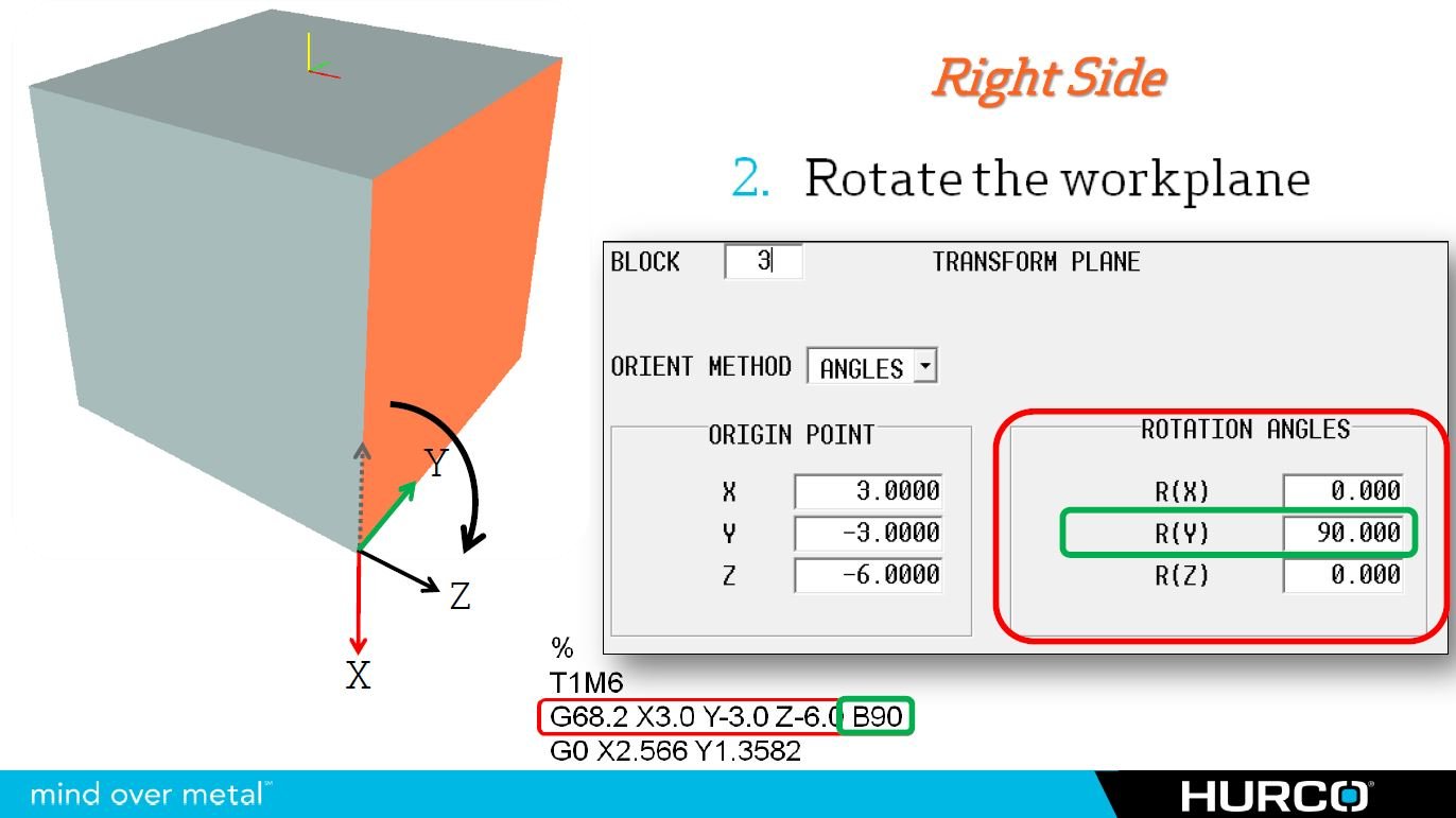
The idea behind creating a 5-axis transform plane using vectors is exactly the same as programming tool movement with IJK tool vectors on any machine with a fifth axis. However, the difference lies in the fact that you will have two separate vectors: one using IJK and the other using UVW. The reason you need two separate “legs” for this function is because you cannot designate a plane with only one axis. I will use the floor inside a room as my analogy: you could not create a floor in a room without having at least two walls. With only one, the floor would simply spin around that single axis and could actually point in literally any direction. To accommodate the two legs of the transform plane, and because we want to determine the direction of the Z-axis ultimately, we will use the X-axis and Y-axis as our legs, or walls of the desired transform plane.

