Absolute Tool Length for CNC Machinists
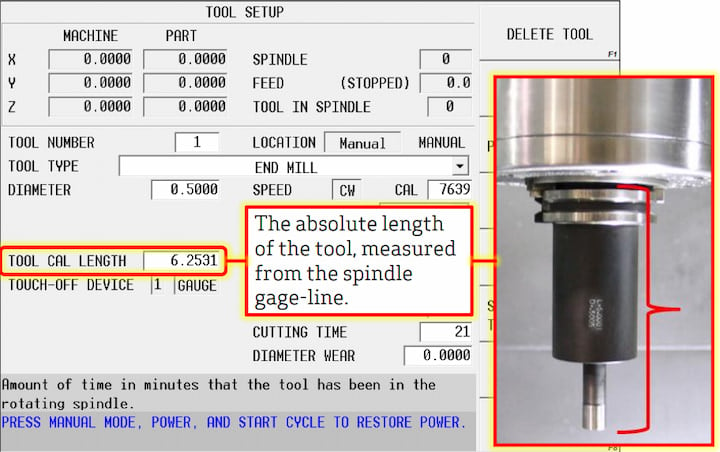
Absolute Tool Length is an industry standard feature in CNC machining that provides continuity across machine brands and controls.

Absolute Tool Length is an industry standard feature in CNC machining that provides continuity across machine brands and controls.

At Hurco, we do whatever we can to support our education and industry partners who are working diligently to attract younger generations to manufacturing and close the skills gap that our industry is currently experiencing.
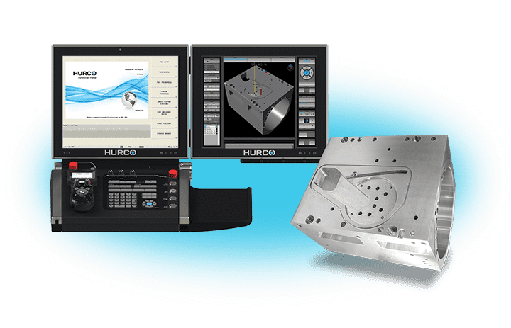
Hurco's 3D Import feature provides the ability to import a solid model directly into the CNC control and conversationally program features from that solid on both 3-axis and 5-axis machining centers.

The ability to import an STL file for stock geometry is a Hurco WinMax feature I'm excited to discuss. Although many people have this feature on their controls, they either aren't aware of it or don't know how to use it. I thought it was worth a quick blog post and video.

CNC Cookbook Survey Respondents Rank Hurco Control #1
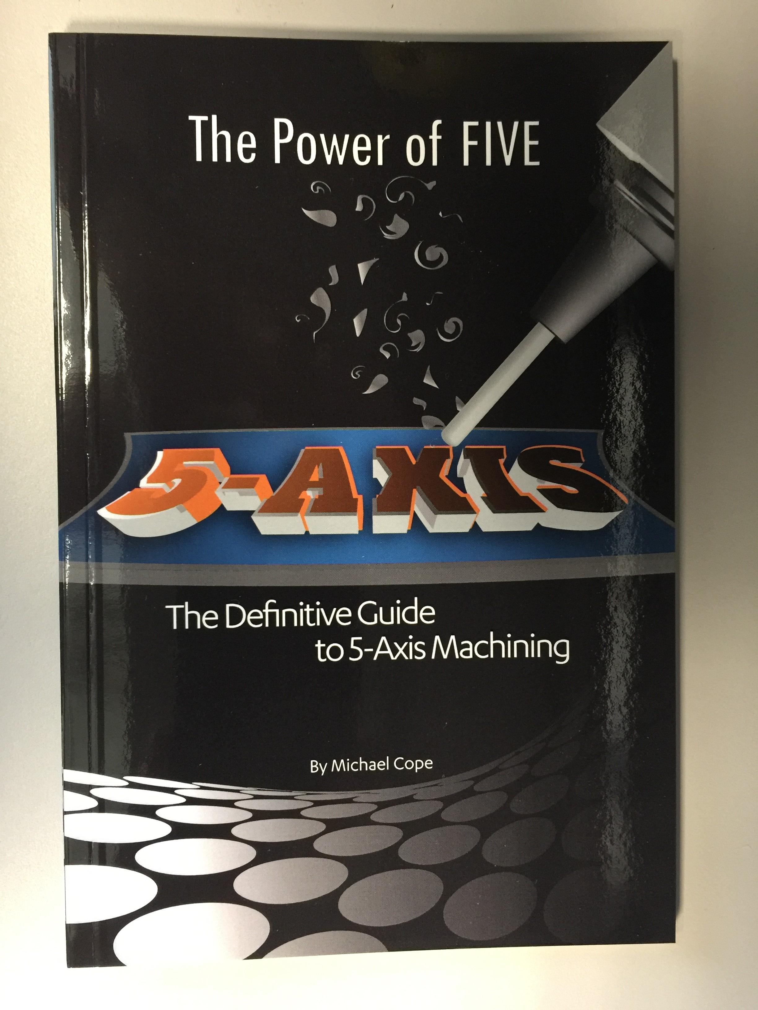
Well I’m just too excited about this not to share this news with my readers. With the help of Hurco Companies, I just recently published my very first actual book! It is a comprehensive guide to 5-axis CNC machining, and I wrote it to help the machinist as a shop floor guide of sorts.
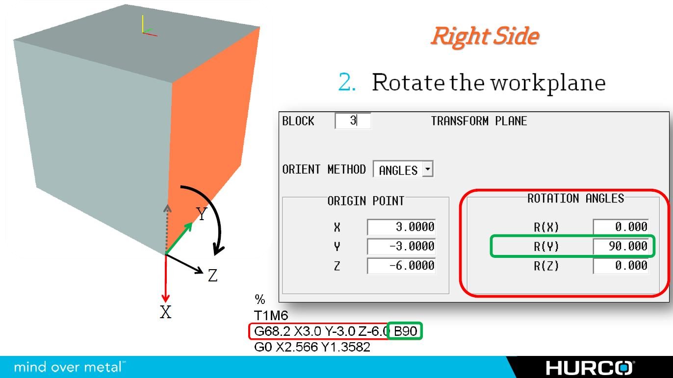
A while back, I received a comment on one of my previous blog posts asking how to designate 5-axis transform planes using IJK UVW vector tokens instead of the traditional ABC rotary axis designations on their 5-axis CNC machine. Instead of just replying to that comment, I thought I would write this post as a response. Since this will be a continuation of the 5-axis CNC basics series, I suggest that you read and understand using IJK tool vectors as a pre-cursor to this article.
The idea behind creating a 5-axis transform plane using vectors is exactly the same as programming tool movement with IJK tool vectors on any machine with a fifth axis. However, the difference lies in the fact that you will have two separate vectors: one using IJK and the other using UVW. The reason you need two separate “legs” for this function is because you cannot designate a plane with only one axis. I will use the floor inside a room as my analogy: you could not create a floor in a room without having at least two walls. With only one, the floor would simply spin around that single axis and could actually point in literally any direction. To accommodate the two legs of the transform plane, and because we want to determine the direction of the Z-axis ultimately, we will use the X-axis and Y-axis as our legs, or walls of the desired transform plane.
Today’s Hurco users are well aware of the term SFQ, or Select Surface Finish Quality, on the Hurco control, and probably have a pretty good idea about which settings work best for them – however, many of them probably don’t realize what is actually going on behind the scenes, and what those settings actually mean or how they affect the machine’s behavior.